Podcasting since 2005! Listen to Latest SolderSmoke

Showing posts with label LtSpice. Show all posts

Sunday, October 22, 2023

DIAL SCALE LINEARITY -- Spreading out the Frequencies for the 15-10 BITX Rig

Click on the image for a better view

The 15-10 Rig has been performing very well, pulling in a lot of DX contacts on both bands.  But there is one thing that has bothered me:  The way the transceiver tunes.  It can be a bit difficult getting an SSB station tuned in properly.  At first I thought this was caused by a lack of lubrication on the variable cap that I've been using (out of an old QF-1), but it turned out that this was not the cause.  The problem is something that Pete Juliano has lamented several times:  LC style analog VFOs have a tendency to have the frequencies "bunched up" at one end of the tuning range.  In other words, the tuning range is far from linear.  I was having trouble tuning stations on on the portion of the band where the frequencies were bunched up.  I did some quick measurement and found that on this side of the capacitor's tuning range, one turn of the dial would move the frequency about 100 kHz -- that is far too much.  On the other end of the capacitor moved  only 22 kHz with one turn of the dial (as I recall this is close to the recommended 20 kHz per dial rotation).  Clearly I had a lot of the dreaded bunching up.  This was what was making tuning difficult. 

I had built a pretty standard Colpitts FET VFO.  I had a 6.6uH coil, and a 9-135 pF variable cap in series with a 68 pF fixed cap.  I was pleased that the VFO worked, and I put it in the circuit.  Only later did the bunching up shortcomings become apparent. 

I decided to build another VFO, this time paying attention to DIAL SCALE LINEARITY. 

I turned to the excellent Bandspread Calculator on Bob Weaver's Electronic Bunker web site:  http://electronbunker.ca/eb/BandspreadCalc.html

I plugged in the frequency range that I needed and the values for my variable capacitor.  I calculated Cs which was the combined capacitance of the feedback and coupling capacitors.  Finally, I had to make a decision about the nature of my variable cap:  was it a Midline-Center Cap or was it a Straightline Capacitance cap.  I consulted with Bob and he suggested that it might be somewhere between the two.  I got out some graph paper and measured it -- it looks to me like a Straight Line Capacitance cap, with the capacitance varying linearly with changes in in the rotation of the shaft. 


It looked fairly linear, so I selected "Straightline Capacitance."  Bob's calculator predicted a much better dial scale linearity (see the picture at the top of this blog post). 

I then built the oscillator stage in LTSpice using the values called for by Bob's calculator: 


It worked well in LTSpice: 

So I built it in the real world.  I didn't have the exact values for the padder and trimmer caps, so I use values that were close. 


Using the frequency counter in my Rigol 'scope, I again measured the frequency change for each movement of the shaft. 

Here are the results: You can see that the bunching up has been largely eliminated.  Frequency change for a 20 degree (not %) movement at one end of the capacitor's range is essentially the same as it is on the other end of the range. 

I will continue to play around with the padder and trimmer cap values to get this VFO where I want it.  I may also have to opt for less frequency range in order to get closer to the desired 20 kHz per dial turn value.  I will also have to play around with the additional capacitance that will be switched in to move the VFO down a bit to the range needed for the 10 meter band. 

The bottom line here is that Bob's bandspread calculator is very useful in figuring out how best to avoid the dreaded bunching up of frequencies that can -- sometimes -- come with the use of analog LC VFOs.  The display of Dial Scale Linearity that appears at the end of each calculation is really brilliant, and allow for an instantaneous look at how changes in the various parameters will affect the linearity of tuning.  This is a really wonderful tool for the homebrewer. 

Thanks Bob Weaver! 

Monday, November 21, 2022

A Homebrew LM386 -- Does Anyone Want to Build It? Help Save Us All from the Indignity of ICs!


I recently commented that I was building a discrete LM386 for a Direct Conversion receiver.  I think I was exaggerating my project.  In fact I just built a very ordinary push-pull amplifier using a 2N3904 and a 2N3906 as a complementary pair AF amplifier.  This is part of an LM386, but there is much more inside that little chip.  Dave went much further.  His schematic is above.  

Here is link to a higher definition image: 

 
Dave writes: 

Hello Bill -


Please find enclosed the LT spice circuit for the small audio amp that I developed.  I have included numerous notes on the schematic as to component function, suggested values to tweak, etc. 

My intention was to come up with a relatively low parts-count design while adhering to the classic three-stage topology [diff pair / voltage amp / voltage follower] that has been used as the basis for so many audio power amplifiers for decades.  I'm sure some of the parts could be eliminated at the risk of possible stability issues, but a lot of that also depends on proper layout, length of speaker leads, speaker load impedance, etc.

In any case I thought it would be great if someone wanted to build up this design to see if it works in real life or whether any serious mods are needed to get it to behave (I have no illusion that the spice models are entirely accurate, nor is my analysis thorough).

It should be capable of at least 500mW into an 8 ohm load at 9VDC supply, and over a watt at 12VDC.  It should handle a 4 ohm load although at reduced voltage swing on the output, and with increased output transistor heat dissipation requirements. 

The output stage is a complimentary compound ("sziklai") pair which should, in theory, maximize voltage swing from a low supply voltage (as compared to the more traditional complimentary Darlington configuration. 

The bias current is set by a fixed pair of resistors and could be quite different from the simulated value, so I would be careful on initial power-up to monitor the quiescent current draw.  I would guess it need not be more than a few mA or so, and definitely less than 40mA or so.  This can be made adjustable if desired.  

Regards,
Dave
-----------------

So, does anyone out there want to give this a try?   You could be helping to save generations of homebrewers from the indignity of using an integrated circuit! 


Thursday, September 15, 2022

SolderSmoke (Old Smoke) Podcast #103 -- March 15, 2009 -- From Rome -- QRSS, Knights and Wizards, LTSpice, and an Echolink QSO with Jeff KO7M (the guy with the Piper Cub)

 15 March 2009 

Beware the Ides of March! 
Ostia Beach and Ostia Antica
248 Knights of QRSS. And Wizards! 
ET Phones Home (with QRSS?) 
Possible new grabbers in VK6 and Dubai
Telescope, Satellites... 
REAL QRP QSOs on 80 and 40
Saving an old Toshiba Laptop
ECHO-QSO WITH JEFF, KO7M: 
-- Piper Cubs and MFJ Cubs
-- Satellite QSOs 
-- LT Spice and test gear
MAILBAG: 
Gene W3PM listens from QE2, HB WSPR rig
Jim AL7V sending parts for my W3PM rig
Jim AB3CV's color burst Gnat
Jason NT7S on Tektronix guys and SolderSmoke
Kevin ZL3KE on old computers
Paul M1CNK's DDS 30-based QRSS beacon
Soeren OZ2DAK on exercise bikes to power beacons

Saturday, June 11, 2022

Putting the "Mate for the Mighty Midget" Back to Work -- With a DX-100 on 40 Meter AM

After working on it for a while I got so fond of my old Hammarlund HQ-100 that I moved it from the AM/Boatanchors operating position over to a more convenient spot right next to my computer.  This left a big gap on the receive side of the AM station.  

I briefly put my HRO-ish solid state receiver above the DX-100, but I'm afraid that receiver needs some work.  More on that in due course. 

I thought about putting my SOLID STATE Lafayette HA-600A atop the thermatronic DX-100, but this just didn't seem right. The Radio Gods would NOT approve. 

So I turned my attention to the Mate for the Mighty Midget that I built in 1998 and have been poking at and "improving" ever since

This receiver worked, but not quite right. It received SSB stations well enough, but when I turned off the BFO I could no longer hear the band noise. I wasn't sure how well the RF amp's grid and plate tuned circuits tracked.  And I had serious doubts about the detector circuit that Lew McCoy put in there when he designed this thing back in 1966. 

As I started this latest round of MMMRX poking, I realized that I now have test gear that I didn't have in 1998:  I now have a decent oscilloscope.  I have an HP-8640B signal generator (thanks Steve Silverman and Dave Bamford).  I have an AADE LC meter. And I've learned a lot about building rigs. 

FRONT END TRACKING

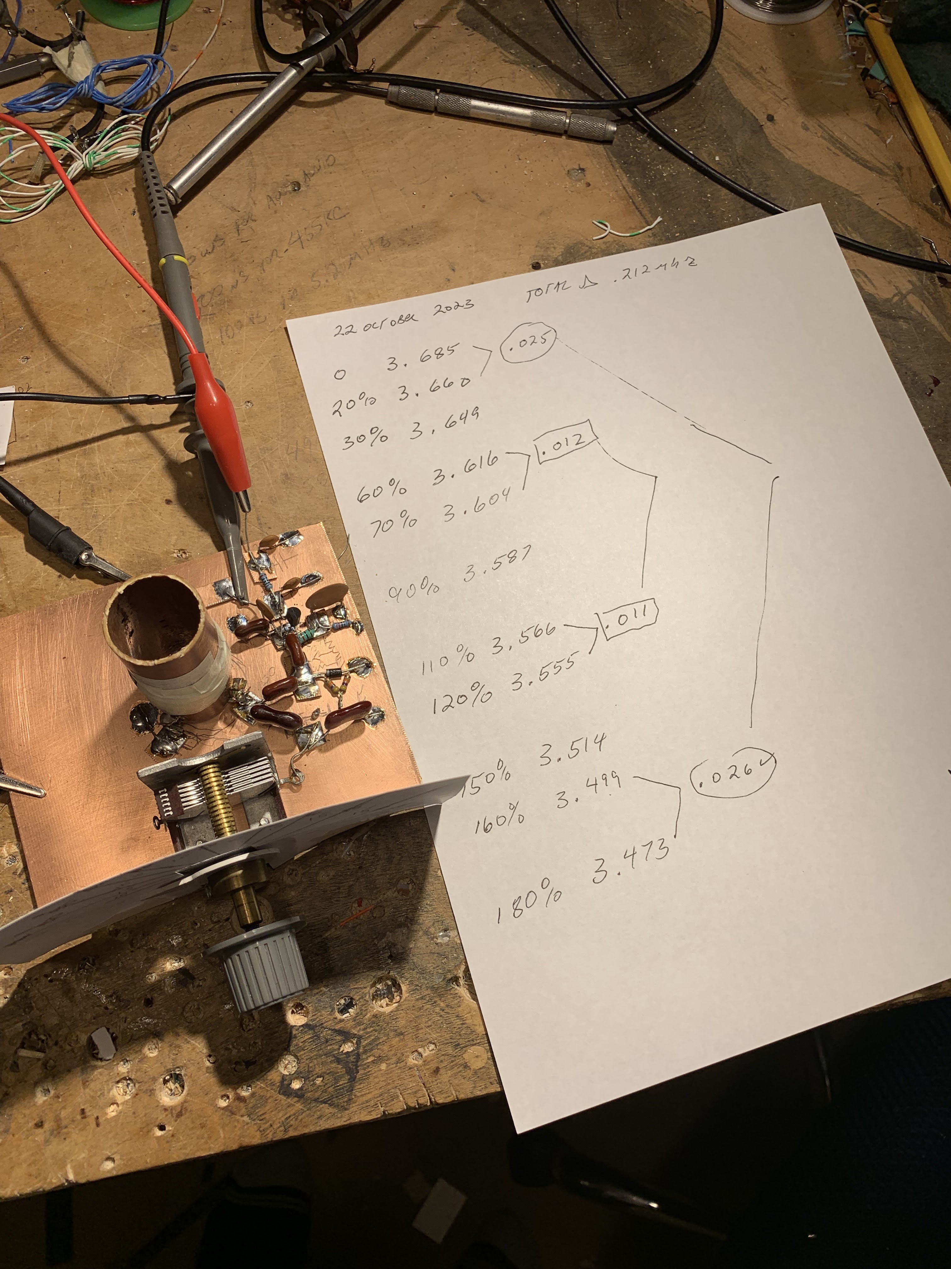
The MMRX has a tuned circuit in the grid of the RF amplifier, and another in the plate circuit of the RF amplifier.  There is a ganged capacitor that tunes them both.  They need to cover both 80/75 and 40 meters. And they need to "track" fairly well:  over the fairly broad range of 3.5 to 7.3 MHz they both need to be resonant at the same frequency.  

McCoy's article just called for "ten turns on a pill bottle" for the coils in these parallel LC circuits.  The link coils were 5 turns.  No data on inductance was given.  Armed now with an LC meter, I pulled these coils off the chassis and measured the inductances of the coils.  I just needed to make sure they were close in value.  They were: 

L1 was .858uH L2 was 2.709         L3 was .930uH  L4 was 2.672

Next I checked the ganged variable capacitors.  At first I found that one cap had a lot more capacitance than they other.  How could that be?  Then I remembered that I had installed trimmer caps across each of the ganged capacitors. Adjusting these trimmers (and leaving the caps connected to the grid of V1a and V2A, I adjusted the trimmers to get the caps close in value.  I think I ended up with them fairly close: 

C1: 63.77-532 pF          C2 64.81 -- 525.1 pF

I put the coils back in and checked the tracking on 40 and on 80/75.  While not perfect, it was close enough to stop messing with it.  

DETECTOR CIRCUIT


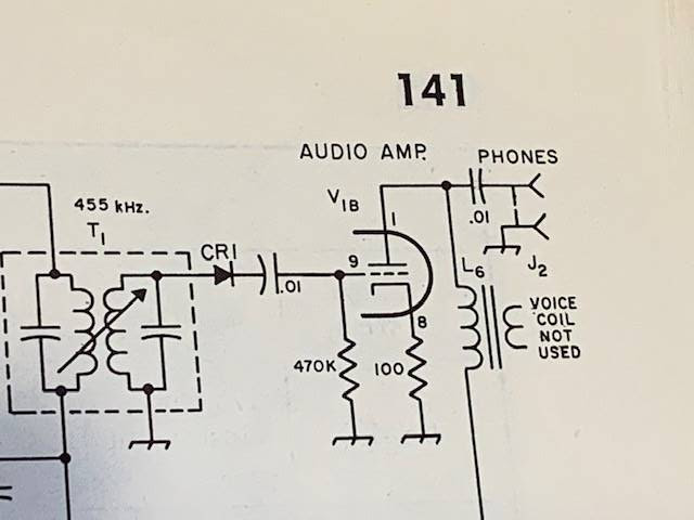
I've had my doubts about the detector circuit that Lew McCoy had in the MMMRX.  In his 1966 QST article he claimed that the circuit he used was a voltage doubler, and that this would boost signal strength.  But I built the thing in LT Spice and didn't notice any doubling.  And consider the capacitors he had at the input and output of the detector:  100 pF.  At 455 kHz 100 pF is about 3500 ohms.  At audio (1 kHz) it is 1.5 MILLION ohms. Ouch.  No wonder years ago I put a .1 uF cap across that output cap just to get the receiver working. 

Scott WA9WFA told me that by the time the MMMRX appeared in the 1969 ARRL handbook, the second "voltage doubling" diode was gone, as were the 100 pF caps.  Now it was just a diode, a .01 uF cap and a 470,000 ohm resistor.  I switched to the 1969 Handbook circuit (but I have not yet changed the 1 meg grid resister to 470k -- I don't think this will make much difference).  Foiled again by a faulty QST article, again by one of the League's luminaries. 

6U8s out, 6EA8s in 

We learned that the 6U8 tubes originally called for by Lew McCoy are getting old and not aging well.  So I switched all three to more youthful 6EA8s.  This seemed to perk the receiver up a bit. 

MUTING from the DX-100

My K2ZA DX-100 has a T/R relay mounted in a box on the back of the transmitter.  When the Plate switch goes up, it switches the antenna from receiver to transmitter.  The box also has a one pole double throw switch available for receiver muting.  I put the common connection to ground, the normally connected (receive position) connect the ground terminal of the AF output transformer to ground -- it is disconnected from ground on transmit.  The other connection (normally open) is connected to the antenna jack -- on transmit this connection ground the receiver RF input connection.  These two steps mutes the receiver very nicely. 

Replacing Reduction Drive

Over the years I have had several different reduction drives on the main tuning cap.  I had a kind of wonky Jackson brothers drive on there that needed to be replaced.  I put in a new one -- this smoothed out he tuning considerably. 

Ceramic Resonator

I never could get McCoy's 455 kc two crystal filter to work right.  So at first I made due with the two 455 kc IF cans.  This made for a very broad passband.  Then I put a CM filter in there.  This was more narrow, but with a lot of loss.  There may have been others.  But the filter spot is currently held by a 6 kHz wide ceramic filter.  This one is my favorite so far. 
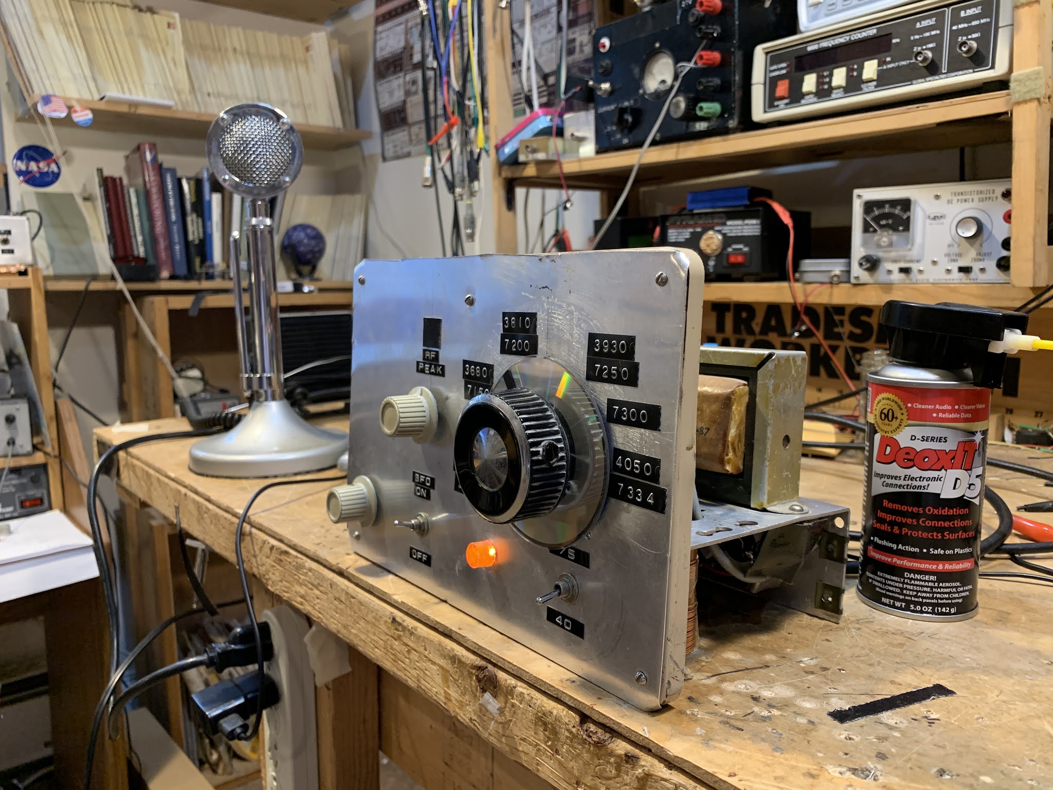
Digital Readout

When I was running the DX-100 with the Hammarlund HQ-100 I built a little frequency readout box.  The box was from a Heath QF-1 Q multiplier (I am sorry about this).  The readouts are in Juliano Blue and come via e-bay from San Jian.  I now have it hooked up to the DX-100's oscillator.  I haven't tapped into the MMMRX's oscillator yet. 


Wednesday, October 13, 2021

SolderSmoke Podcast #233: PIMP, Boatanchors, Novices, MMM, Heathkits, DC Receivers, Mailbag


SolderSmoke Podcast #233 is available. 

http://soldersmoke.com/soldersmoke233.mp3

Travelogue: Cape Cod. SST. Marconi Site.

The WFSRA:   The World Friendship Society of Radio Amateurs.


Pete's Bench:

The Pimp.
The NCX rig.
The Collins.
The many DC receivers built worldwide.
The parts shortages are real! Several key radios on hold. Si5351 sub.
Talk to G-QRP convention

Bill's Bench:

FT-8. Not for me. I tried it.
Novice Station Rebuild.
Globe V-10 VFO Deluxe.
Selenium rectifier removal CONTROVERSY?
Not crazy about my Novice station. Not crazy about CW. 
Mate for the Mighty Midget. Again. 
Mike W6MAB -- Detector problems LTSPICE Check
One more mod for MMM RX. Ceramic filter at 455.
Dropped screw inside tubular cap on Millen 61455 transformer. 
Talk to the Vienna Wireless Society
Thinking of a Moxon or a Hex beam.


BOOK REVIEW Chuck Penson WA7ZZE New Heathkit Book. http://wa7zze.com


Mailbag

-- New SPRAT is out! Hooray!
-- Todd K7TFC sent me copy of Shopcraft as Soulcraft. FB.
-- Dean KK4DAS building an EI9GQ 16 W amp. FB.
-- Jack NG2E Getting close on Pete's DC receiver.
-- JF1OZL's website is BACK!
-- Tony K3DY sent link to cool books. 
-- Sheldon VK2XZS thinking of building a phasing receiver.
-- Peter VK2EMU has joined the WFSRA. FB!
-- Ned KH7JJ from Honolulu spotted the Sideband Myth in the AWA video.
-- Chris M0LGX looking at the ET-2, asks about the variometer.
-- Pete Eaton Nov 64 anti HB rant in november 1964 QST. Wow.
-- Josh Lambert Hurley spreading FMLA stickers in the UK. FB
-- Stephen VE6STA getting ready to melt solder.
-- Got a great picture of Rogier PA1ZZ back on Bonaire.
-- Farhan reading the manual of Hans's new digital rig.
-- Paul G0OER wonders if FMLA getting ready to move on 5 meters.

Sunday, November 22, 2020

Wrapping up the HA-600A Product Detector Project -- Let's Call Them "Crossed Diode Mixers" NOT "Diode Rings"

This has been a lot of fun and very educational.   The problem I discovered in the Lafayette HA-600A product detector caused me to take a new look at how diode detectors really work.  It also spurred me to make more use of LTSpice.  

In the end, I went with a diode ring mixer. Part of this decision was just my amazement at how four diodes and a couple of transformers can manage to multiply an incoming signal by 1 and -1, and how this multiplication allows us to pull audio out of the mess. 

But another part of the decision was port isolation: the diode ring mixer with four diodes and two transformers does keep the BFO signal from making its way back to into the IF chain.  This helps prevent the BFO signal from activating the AGC circuitry, and from messing up the S-meter readings. LTSpice helped me confirm that this improvement was happening:  in LTSpice I could look at how much BFO energy was making its way back to the IF input port on the diode ring mixer.  LTSpice predicted very little, and this was confirmed in the real world circuit. (I will do another post on port isolation in simpler, singly balanced diode mixers.)  

At first I did have to overcome some problems with the diode ring circuit.  Mine seemed to perform poorly with strong signals: I'd hear some of the "simultaneous envelope and product detection" that started me down this path.  I also noticed that with the diode ring, in the AM mode the receiver seemed to be less sensitive -- it was as if the product detector circuit was loading down the AM detector.  

One of the commenters -- Christian -- suggested putting some resistance into the input of the diode ring circuit.  I put a 150 ohm pot across the input, after the blocking capacitor. The top of the pot goes to the capacitor, the bottom to ground and the wiper to the input of L1 in the diode ring circuit (you can see the circuit in the diagram above).  With this pot I could set the input level such that even the strongest input signals did not cause the envelope detection that I'd heard earlier.  Watching these input signals on the 'scope, I think these problems arose when the IF signals rose above .7 volts and started turning on the diodes.  Only the BFO signal should have been doing that.  The pot eliminated this problem.   The pot also seemed to solve the problem of the loading down of the AM detector.  

With the pot, signals sounded much better, but I thought there was still room for improvement.  I thought I could hear a bit of RF in the audio output.  Perhaps some of the 455 kHz signal was making it into the AF amplifiers.   I looked at the circuit that Wes Hayward had used after the SBL-1 that he used as product detector in his Progressive Receiver.  It was very simple:  a .01 uF cap and 50 ohm resistor to ground followed by an RF choke.  I can't be sure, but this seemed to help, and the SSB now sounds great. 

A BETTER NAME? 

One suggestion:  We should stop calling the diode ring a diode ring.  I think "crossed diode mixer" or something like that is more descriptive.  This circuit works not because the diodes are in a ring, but because two of them are "crossed."   From now on I intend to BUILD this circuit with this crossed parts placement -- this makes it easier to see how the circuit works, how it manages to multiply by -1, and to avoid putting any of the diodes in backwards.

I prefer the bottom diagram

A KNOWN PROBLEM? 

I'm left wondering if the engineers who designed the HA-600A were aware of the shortcomings of the product detector.  It is really strange that my receivers lacks a 12V line from the function switch to the product detector. And it is weirder still that the detector works (poorly) even with no power to the transistor.  What happened there?  

When you look at the HA-600A manual, you can see a hint that maybe they knew there was a problem.  For CW and SSB, the manual recommends leaving the AF control at the quarter or halfway point, then controlling loudness with the RF gain control.  This would have the effect of throttling back the RF gain (and the potential for product detector overload) when strong signals appear.  MGC in addition to the AGC.  Any memories or insights on this would be appreciated. 


Tuesday, November 17, 2020

A Diode Ring Product Detector for the HA-600A? Problems.


Pete advised me to try this a week or so ago, but it took me a while to follow through and try it out.  

I got the two diode, one transformer product detector working well, but with it a new problem arose: 455 kHz energy from the BFO was leaking past the product detector back into the S-meter/AGC circuitry.  This showed up in the form of a constant S-3 reading when I switched to SSB/CW.  This was annoying. 

I figured the problem was that the only signal really being balanced out was the IF signal going into L1 of the product detector.  I took another shot at putting the BFO signal into this port, with the IF signal going into the unbalanced potentiometer port.   This did indeed take care of the BFO leakage S-meter problem, but once again the SSB did not sound great -- I think the old problem of simultaneous envelope and product detection returned.  

This was obviously a port isolation problem.  I remembered that the diode ring "doubly balanced" configuration has much better port isolation.  So on Sunday morning I built one, first in LTSpice and then on the bench.  

For the bench model I used some PC board pads out of Pete Juliano's $250,000 CNC machine.  For the toroids I used two trifilar coils wound by Farhan's dedicated staff in Hyderabad.  The diodes were sent to me by Jim W8NSA.  So there was lots of soul in this new machine. 

The circuit worked in LT Spice and at worked well when tested on my bench with my FeelTech (for the BFO) and HP8640B (for the IF signal) sig gens with my Rigol 'scope watching for the audio out.  

But I ran into some problems when I popped the new board in there in place of the old product detector:  The 455 kc BFO leakage problem is gone and the S-meter is where it should be, but...

-- I'm seeing a return of the old simultaneous envelope and product detection problem.  SSB was sounding scratchy again and indeed, when I removed the BFO signal from the diode ring circuit I could hear SSB signals making it into the audio amplifiers.  These signals sounded just like AM signals as heard through an envelope detector without a BFO. 

-- The diode ring circuit also had a very bad effect on how the HA-600A worked in AM mode.  It seemed like the new circuit was loading down the diode AM demodulator.   SW broadcast signals sounded awful in the AM mode until I disconnected the IF input to the diode ring circuit (this input is NOT switched -- it is always connected, even in the AM mode). 

So, for now, am back to using the two-diode, single transformer, singly balanced product detector with IF signal going to the balanced (L1) port and the BFO going in through the wiper of the 100 ohm pot.  

Any suggestions on how to overcome the problems with the diode ring circuit?  


Sunday, August 16, 2020

Fixing up a Radio Shack DX-390 (AKA Sangean ATS-818) While Suffering from Fat Finger Syndrome


I've had this Radio Shack DX-390 portable receiver since the early 1990s.  I bought it when I was in the Dominican Republic.  It accompanied me on some interesting trips to the Haitian border, and on one very memorable 1994 trip to the Haitian capital.  I have made some CW contacts with it serving at the inhaler.  


Click on the diagram for a better view. It is a dual conversion superhet.  First IF is at 55.845 MHz.  There is a big 90's era IC-based PLL oscillator that runs from 55.995 to 118.7 MHz -- The main tuning dial moves this oscillator.  Second IF is at 450 kHz.  There is an oscillator at 55.395 that takes the signal down to 450 kHz. Selectivity (not a lot) is provided by ceramic filters.  Finally there is a product detector and a 450 kHz  oscillator that produces the audio.   While there are many mystery chips in this receiver, there is also a lot of discrete-component analog circuitry in there -- it is kind of a pleasing mix. 


DX-390 Main Board.  Note kludged toroidal replacment for L10 (just above ferrite antenna) 
The old DX-390 suffered a lot of wear and tear.  The case is very beat up.  The most serious problem was that at some point, probably on a cold, dry, winter day in Virginia, static electricity took out the FET in the receiver's front end.  I made a half-hearted effort to fix it, but it never really worked properly.  

I occasionally found myself thinking of this receiver.   I spotted one on e-bay not long ago, and bought it.  This newer one was in very nice shape.  

But that old one was kind of staring at me from the corner of the shack.  "C'mon radio man," it seemed to say, "can't you fix a shortwave receiver?" So this week I took up the challenge.  

First the FET.  I had kludged an MPF102 in there, but that didn't seem to work well.  Internet fora seemed to think that a J310 would do better, so I installed one of them -- it did seem to work better.  (Note:  Pete Juliano likes J310s -- TRGHS.) 


Kludged in J310. And two sets of back to back diodes
During my earlier repair effort I had apparently destroyed the front end output transformer (L10) but I discovered that I had replaced this with a toroidal transformer.  It still worked, so I left well-enough alone. 

I was pleased that the old receiver was receiving OK, but there was a problem:   The "BFO" control wasn't working.  The BFO would come on, but turning the BFO control did not vary its frequency.  

At this point I discovered that while there are many copies of the DX-390 service manual and schematic on the internet, all of them have seriously degraded copy quality right around the parts of the circuitry that I needed to study.  Sometimes Murphy overpowers the Radio Gods. It took me a while to get a useful schematic of the BFO control mechanism. 

BFO is a bit of a misnomer here:  the control actually shifts the frequency of the 55.395 MHz oscillator that drives the second mixer.  See Block diagram above).   There is a varactor diode in the base circuit of a BLT oscillator circuit.  Turning the BFO control varies the voltage going to the varactor thus causing the oscillator frequency to slide up and down.  But mine wasn't moving.  And that was a problem. 

So I dove right in, trying to figure out why it was oscillating, but not shifting in frequency.  At this point I discovered that I too am afflicted with the disease that Pete Juliano suffers from: Fat Finger Syndrome.  That BFO control circuit has a nice big 100k pot, but all the fixed resistors and caps were surface mount and SMALL.  As I poked around trying to troubleshoot, I managed to make things worse.  It turned out that the lead carrying 6 volts to the BFO control circuitry had broken.  But before I discovered this, I managed to do all kinds of damage to the board.  I lifted two PC board  pads (I should have turned down the temperature on my soldering iron).  Then, when I tried to fix this, I managed to put a solder bridge across two parts of the circuit that definitely should not have been connected.  

This resulted in a bizarre BFO situation.  From the center position, turning the BFO to the left OR TO THE RIGHT would move the BFO in the same direction.  So I could tune in an SSB station by turning to the right, or by turning to the left.  That was just not right. 


Lifted solder pads.  And small wires that now bridge the gaps 
Uffff.  It took me a while to find that fault.  While trying to figure this out, I built the circuit in LTSpice just to see what it was SUPPOSED to be doing.   This helped.  Eventually, through careful inspection with magnifying goggles, I found a solder blob, and removed it.  Now all was right with the universe.  Even though I had caused most of the trouble, it was still quite satisfying to fix it. 

Some additional observations on the DX-390. 

-- It really is a Sangean ATS-818 in disguise.   Just look at the marking on the PLL board.  If you can't find a decent DX-390 schematic, just use an ATS-818 schematic. 


ATS 818 marking along the bottom (green) part of the PLL board
-- The service manuals on these receivers are quite good: the include bloc diagrams, detailed alignment instructions, and even voltage charts for all the chips and transistors.  Impressive and useful. 

-- The static discharge vulnerability is hard to understand.  There is so much cool circuitry in these receivers, why not add four simple diodes?   Not wanting to repeat this saga, I went in and put two sets of back-to-back small signal diodes in each receiver: one set on the telescoping antenna, and other at the input for the external antenna.  Curiously, on the newer receiver, it looks like a previous owner had gone in and tried to address this vulnerability -- but he did a very incomplete job.  He just put ONE diode between the external antenna input and ground.  I had always thought that two diodes back to back would give you good protection from static discharge.  And I don't think that single diode protects the front end in any way from discharge coming in from the telescoping antenna.  


This was a good project.  I got more familiar with general coverage dual-conversion receivers.  And I got reacquainted with an old receiver that I liked a lot.   Both receivers could probably use some alignment.  I'll take that up next. 

Thursday, August 6, 2020

How to Sweep, Plot, and Measure Filter Output in LTSpice


The other day Pete N6QW posted a very nice graph of a bandpass filter's passband.  He was using LTSpice.  I realized I had a serious gap in my LTSpice knowledge -- I wasn't sure how to do this.

The charming video from India explains how.  Really useful.

Monday, January 27, 2020

How to Generate an AM Signal (and DSB!) in LTSpice


Pretty cool and very useful.   You can also do this by using the Modulator symbol, but I found this technique easier and more straightforward. 

But be sure to watch all the way to the end of the video.  Early on, he forgets the step that causes the carrier to stay in the simulation, but then shows how to correct this.  In the process we learn how to create a DSB (suppressed carrier)  signal in LTSpice. 

Monday, December 16, 2019

YouTube LTSpice Tutorials

For those who want to get started in circuit simulation, or to improve your use of the LTSpice program:

https://www.youtube.com/playlist?list=PLT84nve2j1g_wgGcm0Bv3K4RSl2Jdjsey

And this one for the inductor:

https://www.youtube.com/watch?v=65fNDRows90&feature=youtu.be

Thanks to Ben  KC9DLM for alerting us to this.

Sunday, June 4, 2017

LTSpice .asc file for the Organic Chip NE602 Rig

A link to the .asc LTSpice file for the NE602 rig  appears below.   Perhaps some brave soul  more skilled in LTSpice than I am might want to turn this drawing into a real simulation.  Some of the parts (like the NE602s) have actual simulated components behind the drawings.  Others (like the relays and the LM741 and LM386) are just drawings.  But go ahead and flesh this thing out.  Who knows, it might come to life in the PC and start making QSOs on 40!

Here is the .asc file:  http://soldersmoke.com/NE602 Rig.asc

Saturday, June 3, 2017

My Organic Chip Rig with an LTSpice Schematic

CLICK ON IMAGE TO ENLARGE

This is a rig that came together through a process of Spontaneous Construction.  It started out with an innocent effort to get  an Organic Light Emitting Diode display to work with an Si5351/Arduino combination.   Then I figured I'd make a superhet receiver with it.  Then Pete said I should make it a transceiver.

Most of my earlier transceivers so closely followed the schematics of Farhan or others that it didn't really make sense for me to prepare a new schematic.  This one was different.  So I decided to prepare a proper schematic.  I tried a few of the free-ware CAD or drawing programs, but each of them had a learning curve at the entrance. So I turned to LTSPICE.  I have already climbed that learning curve.  

The results appear above.  Click on the image to make it bigger.   I'm sure there are errors in there.  And I think some of my parts choices might be less than optimal.  But it works well.

The filter was deigned with the help of AADE software.

The idea of using two NE602s with a filter between them came (I think) from the Epiphyte.

The band pass filters were designed with ELSIE software.

The RF power chain is mostly from Farhan's BITX40 module, with the pre-driver and driver modified for a bit more gain.  Farhan's amp is the most stable power amplifier I have ever used.  It hasn't given me any trouble, even at 20 Watts. Strongly recommended.

The microphone amp is derived from the 741 op amp circuit used in the (in)famous Wee-Willy DSB rig.

The receiver AF amp also comes from Farhan's BITX40Module.

Please let me know if you spot errors or have suggestions for circuit improvement.

A link to the .asc LTSpice file appears below.   Perhaps some brave soul  more skilled in LTSpice than I am might want to turn this drawing into an actual simulation.  Some of the parts (like the NE602s) have actual simulated components behind the drawings.  Others (like the relays and the LM741 and LM386) are just drawings.  But go ahead and flesh this thing out.  Who knows, it might come to life in the PC and start making QSOs on 40!

Here is the .asc file:  http://soldersmoke.com/NE602 Rig.asc


Saturday, February 11, 2017

VK4FFAB's FB Intro to LTSPICE


Rob VK4FFAB wrote a really nice series on how to get started with the LTSPICE circuit simulator.  I'm sure these articles will also have a lot to offer for those of us who've been using LTSPICE for a while now.  Thanks Rob!  

Rob's articles can be found here:

http://vk4ffab.info/lt-spice-for-radio-amateurs/


Saturday, January 28, 2017

SolderSmoke Podcast #193: BITX 40, OLEDs, KWM-4, Noise Abatement


SolderSmoke 193   28 Jan 2017


Report from Pete on BITX 40 Session with California radio club.

Update on the BITX40 Module Revolution
-- Check out the BITXHACKS page.  Send in contributions.
-- BITX20 mailing list very active.
-- Raduino!
-- Interview with Farhan with W5KUB --   Eliminating the commercial gear.
-- BITX 40s on the beach in Australia.  FB

Bench Reports:

Pete:
-- Color Displays!
-- KWM-4
-- OLED MADNESS!

Bill: 
-- Fixing up the old HT-37   HT37 to HT37 QSO with W1ZB
-- Dabbling in VHF with Ramsey Aircraft band receiver.  NOT FUN.
-- Going all IC with Si5351 OLED NE602 rig.
-- BANDSWEEP
-- OLED Noise and the Active Decoupling solution.

Using LTSPICE as a diagnostic or understanding tool.

Of Waterfalls, Homebrew Rigs and Casual Critics on 40 meters. Words of Wisdom from W8JI.

LEXICON:  HAYWIRE   TOMBSTONE    BIKESHEDDING from Todd K7TFC

Some great recent interviews by Eric 4Z1UG:
Ian G3ROO  Origins of ROO   Regen at age 8
Hans Summers G0UPL     Balloons!   NO COMMECIAL GEAR
David White WN5Y          ELECTROLUMINESCENT  RECEIVER EXPLAINED
Rob Sherwood NC0B 

MAILBAG: 

Chris KD4PBJ's BITX 40 with improved stability
Jerry W0PWE built a DIGITIA!  Very nice.  Worked Keith N6ORS and heard me! TRGHS
Mike AB1YK's Al Fresco Scratch built BITX.  But give that LC VFO another chance Mike!
Steve N8NM 30 meter rig with salvaged CB LC VFO. FB
Keith N6ORS Franken SDR rig with parts from the 1980s.  FB
SKN Bandscan from Mike WA6ARA  I worked W1PID Jim!
What is Mikele up to?
Rocking Johannesburg and Kirghizstan via local repeaters:


Friday, October 28, 2016

Another Great DSB rig from New Zealand


So many great Double Sideband projects come from Down Under.  There are the various versions of the famed ZL2BMI rig.   And Peter Parker VK3YE has long been the acknowledged guru of DSB. In fact, Peter sent me an enthusiastic e-mail about the new ZL DSB rig pictured above -- his e-mail arrived before the message (below) from the intrepid builder.  I detect a bit of the "Tucker Tin" influence in this rig. (But perhaps this one is more Tupper than Tucker!)  Charlie's work has graced out blog posts before: http://soldersmoke.blogspot.com/search?q=zl2ctm
Be sure to check out his video:   https://youtu.be/JsAuWGkyvmE   (and below).


Hi Bill.

You asked recently on the podcast for listeners to let you know what they had on their work bench. Well I’ve been working on a tramping (hiking) radio, which is now complete. It’s a DSB 5W rig designed for 80, 40 and 20m, as well as our New Zealand mountain safety radio system. I designed everything in LTSpice as was suggested by Pete, N6QW. That was great, as I could ‘desolder’ components with the mouse and instantly see what impact it had on the output. An amazing tool that’s free! I highly recommend it.

Once again I’ve used upside down strip board for each stage, which are tacked down onto an un-etched copper board (earth plane). That seems to work really well for me.

The rig uses an Arduino mini driving a small OLED screen and a Si5351 DDS. The Si5351 is going straight into a SBL-1, which seems to work fine too. The AF strip is a 2N3904 before a LM386, which has enough drive to run a speaker. The TX amplifier is a three stage one with shielding between each stage. It’s made up of two 2N2222A stages followed by a BD139. That in turn is followed by three simple filters, one each for 80, 40 and 20m.

All-in-all it works really well. I’ve uploaded a quick video at https://youtu.be/JsAuWGkyvmE

The next project will be a proper SSB rig using a crystal filter salvaged from an old Codan 7727. Like this one, it will use an Arduino and a Si5351.

Finally, I am certainly no expert in homebrew, but I hope my ‘dabbling’ will help inspire others to pick up the soldering iron and give it a go. If I can do it, then anybody can! There is certainly a great sense of achievement to operate a rig you built yourself.

Regards, and thanks to you and Pete for all your inspiration.

73’s
Charlie
ZL2CTM


Monday, August 1, 2016

Walking the Plank with N8NM's 60 Meter Rig

Steve N8NM writes:

The free-range rig is coming along!  I'm receiving with decent sensitivity (my generator's only calibrated to -100 dB/m, and I hear a CW note there just fine) and I'm getting about -2 dB/m out of the mixer.  Yippee!
I ended up using an IF of 20 MHz, mainly because I had a bunch of crystals left over from my Minima.  The architecture (left to right) is: Diode ring mixer using 1N4148s, 20dB W7ZOI bilateral TIA, 6 pole crystal filter (BW ~= 2.3 KHz), Another 20dB bilateral TIA, 1N4148 product detector (cribbed from the Minima), 2N3904 audio driver, LM380 PA.  Microphone amp is two FET stages (J310).  Oscillators are courtesy of an Si5351, controlled by an Arduino Uno.  T/R switching is done using a couple of counterfeit 2SC1969 RF transistors that, ironically, don't amplify at RF, but work fine as power supply "pass" transistors.
Yet to do is the PA, which I've noodled in LTSPICE (shooting for 20W PEP using a bunch of BD139s, just because...) and cleaning up my Arduino sketch.  Right now, I just modified the start-up values of the sketch from my all-band rig for testing.  Since that code is pretty full featured (dual VFOs, RIT, filter switching, LCD Display, etc.) using multi-function pushbuttons to select all sorts of crap, I'm betting that 80% won't be used in this rig.  Adding simplicity is always good.
So, nearing the end, I'm already thinking about my next rig (that and building a 60m antenna...)  I think this one will be similar to my "all band" rig, but limited to the WARC bands (I have a WARC tribander that's screaming for a rig of it's own.)  That's kind of boring, so, to challenge myself, I'm going to try using a touch screen in lieu of the usual pushbuttons.  What would really be cool, though, is an interactive slide-rule dial - don't think anyone's done that before!  One of the things that has always drawn me to the SX-101 is that large slide-rule dial.  To me, that allows each station to occupy a physical place on the dial, so after scanning the band, you know were everyone is.  It's really a joy to operate those rigs!
73!  Hope to work you HB2HB on 60M soon!
-Steve

Saturday, November 21, 2015

SolderSmoke Podcast 182: Bears! MMM Update, On Pete's Bench, 160 AM Dreams, MAILBAG


20151116_091050[1]
N6QW Selfie
SolderSmoke Podcast #182 is available


Travelogue:  In Shenandoah with BEARS!

Michigan Mighty Mite Update and a Generous Offer (with conditions).

BENCH REPORT:
-- Pete's Ten Tec Conversion using LTSpice
-- Pete's Simple-ceiver
-- My CB to 10 conversion plans

DREAMS OF 160 METER AM:   KB3SII, N2CQR, N6QW Building for Top Band

Raspberry Pi Nightmares

Homebrew to Homebrew (HB2HB) Contacts

Elser Mathes Cup -- We have some competition!

QST, "The Radio Art,"  and The Channelization of HF Bands

WA5BDU Nick Kennedy on QSO Today  Podcast

Ed Walker of "The Big Broadcast" was a ham:  N3HFT

MAILBAG:  A Letter from Turkey: Tubes and R-390s
Si5351:  G4GXO says give it a go!


Wednesday, April 8, 2015

Termination Insensitive BITX Amps


 Back in 2009 Wes Hayward and Bob Kopski designed a termination insensitive amplifier block for use in BITX-like transceivers. Farhan urged me to use it.  The advantage of this design is that the input impedance stays at 50 ohms no matter what you hang off the other end.  That's very helpful, especially when you start trying to get specific impedances at the ends of crystal filters.   I'm planning on using this circuit in my next BITX.   This morning I was playing around with it in LTSPICE.  The "mirror" feature in that program is quite helpful when you are working on circuits like this!

Here is the article by Wes and Bob that describes this great circuit:
http://w7zoi.net/bidirectional_matched_amplifier.pdf

Our book: "SolderSmoke -- Global Adventures in Wireless Electronics" http://soldersmoke.com/book.htm Our coffee mugs, T-Shirts, bumper stickers: http://www.cafepress.com/SolderSmoke Our Book Store: http://astore.amazon.com/contracross-20

Friday, March 23, 2012

NJORP's "Chat with the Designers" Podcast

N2APB and N2CX of the New Jersey QRP Club have been hosting weekly, live, on-line technical discussions called "Chats with the Designers." They are recording these sessions, and turning them into -- in effect -- podcasts. Yesterday I listened to their session on circuit simulators and really enjoyed it. Today, I'll be listening to the one on digital modes. I think you guys will like this. Lots to learn from the NJQRP guys:
http://www.njqrp.org/teamspeak/TeamspeakChat.html


Our book: "SolderSmoke -- Global Adventures in Wireless Electronics"http://soldersmoke.com/book.htmOur coffee mugs, T-Shirts, bumper stickers: http://www.cafepress.com/SolderSmokeOur Book Store: http://astore.amazon.com/contracross-20
Designer: Douglas Bowman | Dimodifikasi oleh Abdul Munir Original Posting Rounders 3 Column